


Opinion
Developing A Novel Solution for Measuring Weight - Part 1
Published on 11 Sep, 2023 by Neil
CUSTOMER REQUIREMENTS
A customer was developing a product using a low-cost strain gauge as a weight-measuring element. For the most part, the strain gauge performed well but was susceptible to drift and variations in reported weight due to temperature change. Several attempts to improve the performance of the strain gauge were made in software, but ultimately this was compensation to a non-ideal system.
Green Custard worked closely with the customer and agreed to investigate alternate solutions to replace the strain gauge.
PROPOSED NOVEL SOLUTION
A strain gauge uses a resistive element which changes resistance as it is deformed. This change in resistance can be measured by applying an excitation voltage. The change in voltage is small, typically in the millivolt range, amplified and converted using a high-resolution ADC.
The proposed solution uses an LC oscillator which has a ferrite material inserted into a coil proportionally to the applied weight. This increases the coil’s self-inductance and the oscillating frequency will decrease as some function of the ferrite insertion depth.
The output frequency can be conditioned into a square wave of the correct amplitude and then directly counted by a peripheral in a microcontroller. A very accurate measurement can be made if the frequency is sufficiently high (tens of kHz). The measured frequency can be converted into a weight following a calibration step.
IDENTIFY RISKS
A key part of the investigation is to determine if a particular property fails to meet the requirements. The following characteristics were identified as vital to the success of the proposal:
- Temperature coefficient
- Linearity
- Reproducibility
- Interpolation using a limited table of points
- Frequency measurement accuracy using a low-cost microcontroller
BACKGROUND
A brief overview of some material and electrical basics is provided here which is required to understand the operation of the displacement sensor. No assumption is made on behalf of the reader and only the essential parts will be described.
INDUCTOR
An inductor is a circuit component with the property of having an inductance. It stores energy in the form of a magnetic field. A simple inductor consists of a coil of copper wire wound around a non-magnetic former. This configuration is called a solenoid.
PERMEABILITY
The level of magnetisation of a material in an applied magnetic field. Different materials have different levels of permeability.
- μ is the permeability of a material;
- μ0 is the permeability of free space (an ideal vacuum);
- μr is the relative permeability and is found from:
- μr = μ/μ0
Typical values of μr for common materials:

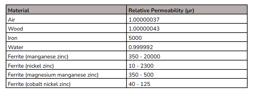
Notice that an inductor immersed in water will have a lower inductance than if it was in air its relative permeability is less than one.
The relevance of a magnetic material with a high value of μr is that if the material is introduced into the coil of an inductor, the inductance will increase markedly and proportionally to the level of insertion
FERRITES
These are a class of ceramic materials used in the cores of alternating magnetic circuits. The μr value is not as high as steel, but they come into their own for high-frequency operation. The Eddy current loops are bigger than the particle size of the magnetic material within the ferrite. This reduces internal losses as there is a limited electrical path for the Eddy current to flow. Ferrite cores are found in magnetic circuits which operate at low-kHz up to multi-MHz.
CAPACITOR
A circuit component with the property of having capacitance. A capacitor stores energy in the form of an electric field and typically consists of two conductors separated by an insulator. The insulating layer is called the dielectric.
The equivalent of relative permeability in a capacitor is relative permittivity. This is the ratio of the permittivity of a dielectric to the permittivity of free space (or an ideal vacuum). It indicates how the capacitance can be increased (for the same surface area and distance between conductors) for a given dielectric. The capacitors have a fixed value in the proposal described here.
PARALLEL LC CIRCUIT
The diagram below shows a typical parallel LC circuit:
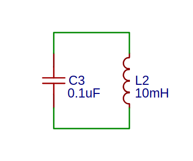
The two electrical components store energy, but not at the same time. As a system, it is analogous to a pendulum where energy is transferred from one form, say kinetic energy, to another, gravitational potential energy. With a fixed value of C3 and a variable value for L2, the resonant frequency can be adjusted by varying L. The term that is used to determine the resonant frequency is:
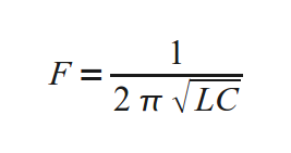
In the example circuit above the resonant frequency, f, would be 5.0329kHz. At higher frequencies, a small change in L can produce a large change in f.
COLPITTS OSCILLATOR
This is a simple oscillator that comprises a gain element (either an operational amplifier, bipolar junction transistor or field effect transistor) with a split capacitive feedback network. A typical implementation is below:

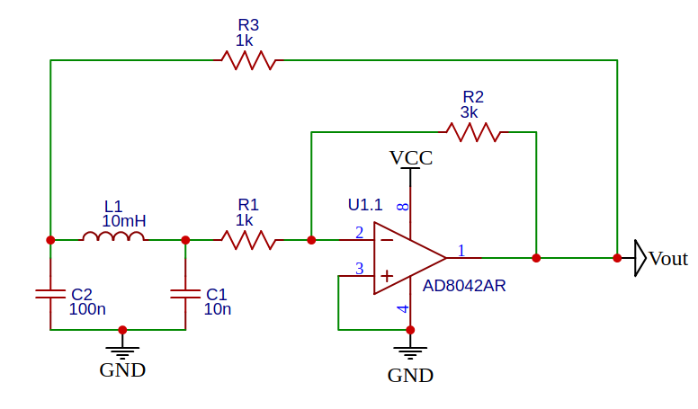
By choosing the inductive and capacitive components carefully, the oscillator can be set to freerun at ~100kHz. This is well within the range of a microcontroller’s SMT capabilities. The inductor (L1) will be the solenoid which is part of the displacement sensor. Notice that this design uses a single supply rail which REDUCES the complexity and cost of the power supply section.
MECHANICAL DESIGN
Below is the basic mechanical design showing the relationship between the weighing deck, which supports the object being weighed, the ferrite core which has a degree of freedom in the z-plane and the springs which provide a return force to resist the weight and allow the ferrite to move downwards a function of the weight applied.

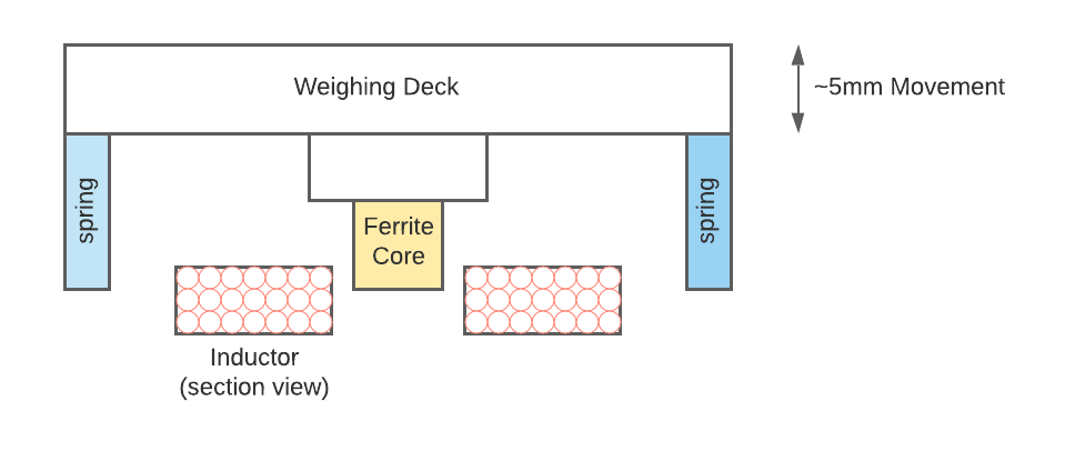
The downwards movement can be several millimetres and this will insert/remove the ferrite core from the solenoid. This change in inductance due to the high μr of the ferrite will cause the oscillator to resonate at several kHz higher or lower depending on whether mass is added or removed. The output signal of the oscillator can be converted to a square wave and then directly counted using a dedicated microcontroller.
OSCILLATOR DESIGN
A Colpitts oscillator was chosen as it uses two capacitors in parallel with a single inductor. If the value of the inductor is altered then the output frequency will follow the change in inductance. The following is a description of the design approach taken to produce a variable Colpitts oscillator suitable for evaluation in a Displacement Sensor.
OSCILLATOR REQUIREMENTS
- The oscillator should be sensitive to changes in inductance due to the slow insertion of a ferrite rod with a high relative permeability (μr);
- The inductor should be physically small to keep the measuring system compact;
- The free-running frequency of the oscillator (without the ferrite inserted) should be of the order of 100kHz to allow for direct measurements of the output using a Microchip Signal Measurement Timer peripheral;
- The oscillator should be of a single-rail design rather than requiring positive and negative power supply rails;
- The oscillator should easily self-start;
- The loop gain at the oscillating frequency should be high enough to sustain oscillation, but not too high that the output stage in the operational amplifier saturates, introducing a clipped output and multiple odd harmonics. THD is not an issue as the output will be conditioned into a square wave anyway, but a clean sine wave indicates good design.
INDUCTOR FORM FACTOR
The starting point is the inductor design. Below is a diagram which shows three inductor form factors:

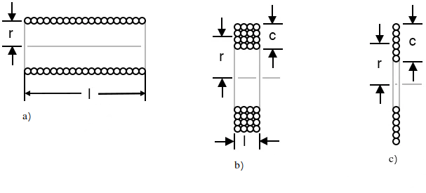
- a) is a single-layer solenoid where the conductor is wound as a helix along a former;
- b) has a square aspect ratio where the sectional height of the coil is the same as the
sectional width of the coil (I == C); - c) is a pancake winding where a single layer is laid on top of the previous turn. The same technique is employed by the Navy when winding ropes.
The ideal design would use form a) as the insertion of a ferrite core would have the maximum change in inductance. The magnetic field generated by each turn would pass through the core (if the core was of sufficient diameter). The problem with form a) is that the inductor would be too long.
Form c) is the worst case as the turns towards the outer radius would not add to the magnetic field penetrating the core. The inner turns would contribute, but the outer turns less.
The best compromise for the inductor design is form b) as it has a reasonably compact shape and the contribution of the ferrite core to the overall inductance will be significant.
Ideally, this design would be modeLed in an electromagnetics solver such as OpenFOAM magnetic Foam, but this is beyond the scope of this investigation!
FORMER AND FERRITE CORE
TDK manufactures a series of coil formers for the fabrication of inductors to your own specifications.
Fair-rite is a manufacturer of ferrite products including an 8x45mm rod made using material 61. These parts are readily available from RS Components.
The drawing for the TDK RM 8 former is below:

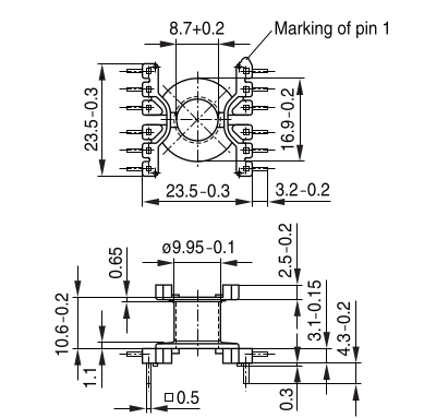
The important points to note are the internal aperture which is 8.7mm and suitable for an 8mm ferrite rod (with a radial clearance of 0.35mm if the nominal dimensions of the former are used).
The next important value is the inner dimension where the coil will start. This is 9.95mm.
Finally, the height that the winding can sit, which is more difficult to establish, but is found by:
10.6 - (1.1 + 0.65) = 8.85mm.
The maximum layer length is determined by:
(16.9 - 9.95) / 2 = (6.95) / 2 = 3.45mm.
Therefore the maximum coil volume is 3.45 x 8.85mm on this former.
Summary
In this first post, we have described the proposed solution using a variable inductor as a weight-measuring element. We've looked at the basic circuit design and mechanical considerations.
The next post will describe some basic circuit simulations and initial measurements.