


Opinion
Developing A Novel Solution for Measuring Weight - Part 2
Published on 20 Nov, 2023 by Neil
In the last post, we described the proposed solution using a variable inductor as a weight-measuring element. We've looked at the basic circuit design and mechanical considerations.
In this post, we will describe some basic circuit simulations and initial measurements.
Multilayer Inductor Calculations
The most famous formula for determining the inductance of a coil is Wheeler’s formula but modern numerical solvers can produce more accurate results. Here we use https://coil32.net/online-calculators/multilayer-coil-calculator.html which uses Maxwell’s Equations with elliptic integrals.
The Quality Factor
The quality factor (or simply Q-factor) of an inductor is the ratio of the initial energy stored in the inductor to the energy lost over one full radian of the oscillation. To relate this to a more meaningful system, imagine hitting a thin wine glass which resonates for some time compared with hitting a mug with the same energy which only resonates for a fraction of the time. The wine glass has a high Q. Ideally we want the Q-factor for the inductor to be as high as possible as this will give a very pure oscillating frequency and it is this that we are
measuring to determine displacement.
The diagram illustrates the benefits of a high Q-factor:

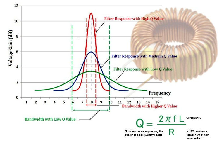
The resistance of the coil R, is the quantity which lowers the Q, a high R, a low Q.
Now the next compromise, we need a reasonable value of inductance, which implies many turns, but it has to fit within the former. If we use many turns, we will have to use a wire with a small cross-sectional area (CSA) which implies a high R. To understand the effect the Q has on the oscillator, four inductors will be made using wire of differing CSAs.
Three reels of enamelled copper wire were sourced of differing CSA to understand the effects of Q on the circuit behaviour.
DETERMINING THE INDUCTOR VALUE
A requirement is that the oscillator should run at approximately 100kHz. This is low enough that exotic (expensive) active elements are not required (a device with a gain-bandwidth product of 8MHz was chosen), but high enough to allow for accurate measurement by directly counting each oscillation over a gated time period. Polypropylene film capacitors provide reliability and lowdrift. The value of the inductor needs to be such that capacitors can be sourced that provide a resonant frequency in the range required. A value of 500μH was chosen for the inductor and then the circuit was simulated.
LTSPICE
This is a free application that can run on Windows or Linux under Wine. It provides basic schematic capture and simulation of a circuit design to determine component values and other metrics about the circuit.
SINGLE SUPPLY RAIL COLPITTS OSCILLATOR
The simulations are run against the following circuit:

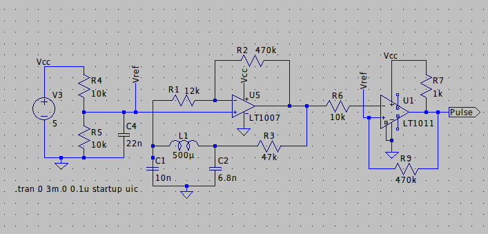
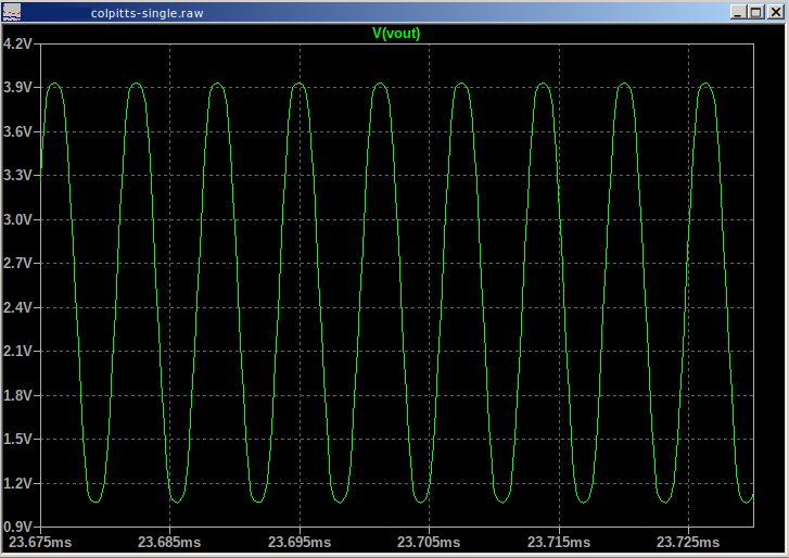
The supply voltage is set at 5Vdc (V3) and the resonant circuit comprises C1, C2 and L1. L1 will be the variable inductor in this application. The following image shows the output (Vout) from switch-on to 3ms.

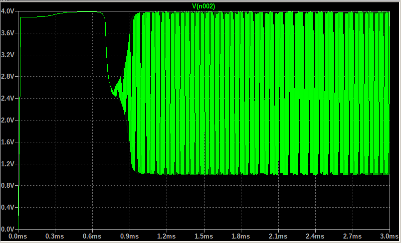
A closer look at the waveform reveals the following details:

COIL CALCULATIONS
Now that we have a target value for the inductor (500μH) and the coil former dimensions, we can determine how many turns and layers are required using 0.15mm diameter enamelled copper wire.

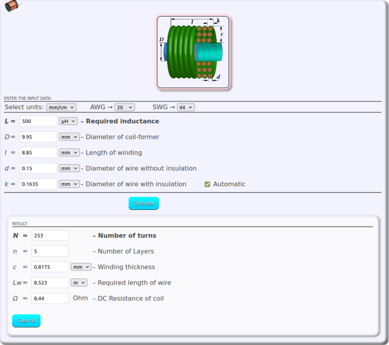
Dimension c is less than 3.45mm so this coil will fit on the former and 253 turns are required for a 500μH inductor. This inductance is for only the coil, it will increase when the ferrite core is inserted.

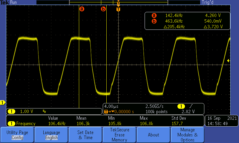
Frequency is 106.28kHz, peak to peak amplitude is 3.72V. The waveform is not perfect as it should be a clean sinusoid, but this can be addressed later if required.
Analogue electronic design is a combination of science and art. Certain elements can be designed or measured in a specific configuration to a high degree of accuracy. Equally, elements can be designed which upon test do not work as expected. The reason for this mismatch between engineering design and reality is that the underlying physics used is often an approximation. Models can be made and simulations run, but the real world will provide the truth when the circuit is built and tested.
By carefully measuring the Q-factor and building multiple coils with various diameters to test, we can put theory into practice and develop the most accurate displacement sensor possible within the confines of the specification.
In the next blog, we'll explore the initial measurements and investigate the change in frequency as a function of temperature.