


Opinion
Developing a Novel Solution for Measuring Weight - Part 5
Published on 20 Feb, 2024 by Neil
In the previous post, we looked at the data quality, the reproducible values, and the effect of temperature on the measurement. As the data is non-linear, we investigated two methods to interpolate to get a good mapping between frequency and the applied mass (displacement of the weighing platform).
In this final post, we will look at the design of a board that converts frequency into displacement using a Microchip part that can directly count the input over a gated period.
Low-Cost Frequency Measurement
Microchip manufactures a family of advanced 8-bit microcontrollers (the 18F range) some of which contain a Signal Measurement Timer peripheral. This peripheral is designed for interfacing time-varying signals to the microcontroller and can be configured to operate in multiple ways. Microchip describes the peripheral as follows:
The SMT is a 24-bit counter with advanced clock and gating logic, which can be configured for measuring various digital signal parameters such as pulse width, frequency and duty cycle, and the time difference between edges on two signals. The device has only one SMT module implemented.
Features of the SMT include:
- 24-bit timer/counter
- Three 8-bit registers (SMT1L/H/U)
- Two 24-bit measurement capture registers
- One 24-bit period match register
- Multi-mode operation, including relative timing measurement
- Interrupt on period match
- Multiple clock, gate and signal sources
Interrupt on acquisition complete
The block diagram for the SMT is below:

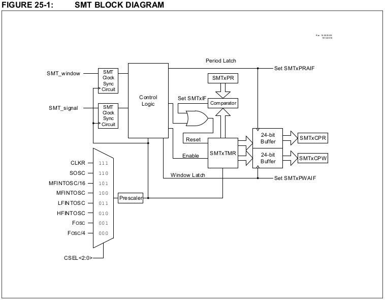
Interesting points are:
- SMTxWIN is the internally generated window signal. It is derived from Timer2 pre- and post-scaled to provide an approximate 1s gate (it is slightly less than 1s, but repeatable);
- SMTx_signal is the input signal (conditioned output of the oscillator) to be counted;
- SMTxCPR is a 24-bit register that contains the number of counted pulses following a transition of the SMTxWIN signal.
The final schematic for the complete prototype is below:

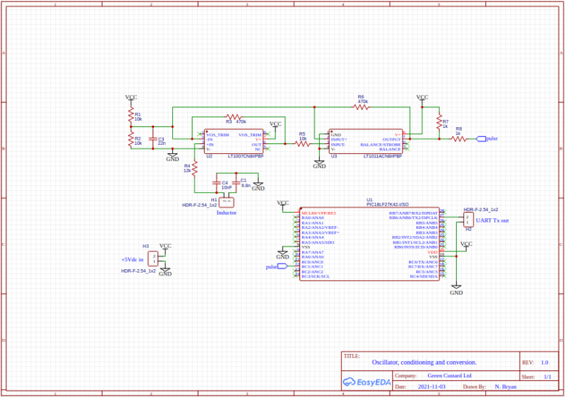
The bulk of the software running on the PIC18F27K42 is used to configure the various peripherals.
The main loop is below:
while (1)
{
__delay_ms(800);
uint32_t cpr = SMT1_GetCapturedPeriod();
sprintf(buf, “%03lu\r\n”, cpr);
UART2_sendString(buf);
}
This simply spins for 800ms, then reads the last captured count of pulses acquired during the gating period and then sends this data out over a serial port. The timer counter is copied by internal logic within the SMT so reading SMT1_CPR captured period register does not affect the current data acquisition.
The chart below shows 800s worth of data:

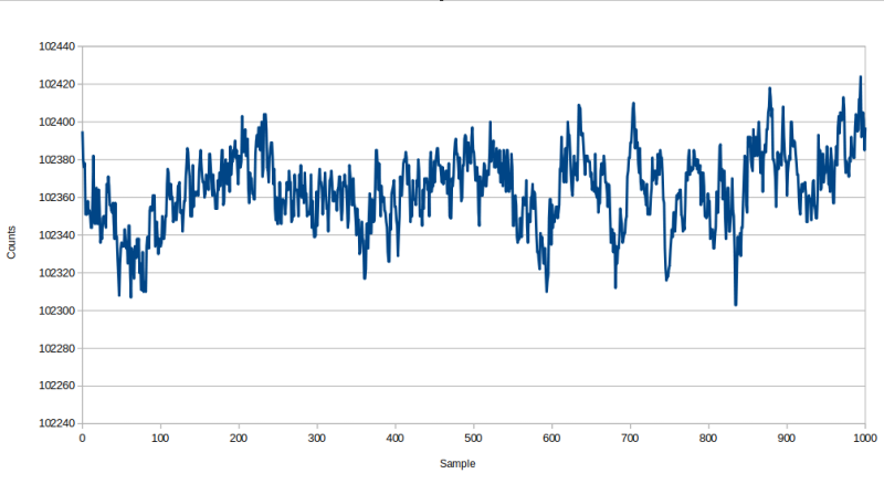
The chart shows a variation of 121 counts (the difference between maximum and minimum counts).
The stability demonstrated using the Agilent 34410A showed a variation of a ~5 counts for a constant temperature. The reason for the wide variation using the SMT is not clear at this stage and further investigation is required. It is most likely due to variation in the clock source for the Microchip part.
PBC Design
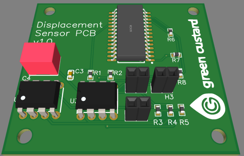
Using the captured schematic, a representative PCB was designed which can be seen below:

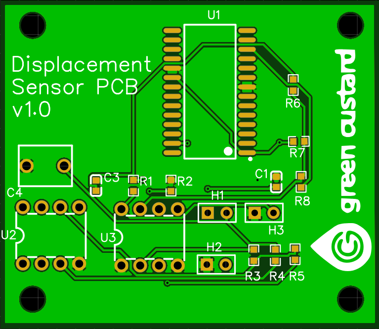
A 3D model can be generated which is useful for designing a suitable enclosure, although KiCad offers a superior export feature than EasyEDA.

The original motivation for the development of a displacement sensor based around an LC oscillator was to establish if a method for determining weight with a lower temperature coefficient was possible. The principle was proved and this approach was viable although further work was needed to reduce the spread of measured counts. A better quality crystal oscillator for the Microchip part would be trialled next.
During the development, the strain gauge solution was looked at and an alternative way of triggering was investigated. Ultimately this proved to be sufficiently reliable and the displacement sensor was not developed further. The work has been done and it can be continued at short notice if required.